It can overheat more easily than copper and start electrical fires by slowly damaging its insulation and heating things around it. Look for the printed or embossed markings on the outer insulation, or jacket, of the wires.
Amazon Sells Color Aluminum Wire Garden Bonsai Wire Aluminum Wire - Buy Bonsai Wire,Aluminum Wire,Color Aluminum Wire Product On Alibaba.com
Earliest uses in germany ca 1930.

What color plastic is on aluminum wiring. Some people suggest wrapping them with electrical tape. When all the aluminum atoms have. Copper clad aluminum wire identification.
The nec does, however, require that wire size be imprinted in the repeating data strip running along the sheathing. It has one stable isotope, 27 al; White and gray electrical wires.
Utility companies have used aluminum wire for electrical transmission in power grids since around th… Always assume that a red or orange wire. Is rated at 200 amps.
£1.58 exc uk vat (£1.90 inc 20% uk vat) 1.50mm red colour enamelled aluminium craft wire 3 metre coil 2mm green colour aluminium craft wire ref: Cpsc research shows that homes wired with aluminum wire manufactured before 1972 are 55 times more likely to have one or more connections reach “fire hazard conditions” than are homes wired with copper. Any other colors expected the above mentioned can be.
With a higher tensile strength, copper wiring is less likely to break than aluminum wiring. This is important considering that electrical wiring is often installing by pulling it through ports and feeders. The code you need to input is #888b8d.
“post 1972” aluminum wire is also a concern. Each wire used for electrical wiring is marked with information like wire gauge, ampacity, maximum voltage, and maximum temperature. Aluminum wires are the color of aluminum and are easily discernible from copper and other metals.
Wires with aluminum conductors will have “al” or “aluminum” and other information marked every few feet along. The incoming 240v power is split into two legs. The service coming to an ideal house in the u.s.
If the wiring is weak or fragile, it may break during installation. Studies show that only 0.05 amp of electric current can cause heart attack and skin damage and high probability of death. Once the wires have been stripped place the wire nut over the two wires together.
In case of a single phase power supply. Without question a corrugated sign is meant to be a budget sign alternative. Some aluminum wire has the word aluminum or a specific brand name such as kaiser aluminum plainly marked on the plastic wire jacket.
Thankfully, the hex value for aluminum is simple; The mandatory colors for power wiring in national electric codes (nec) are green, bare or green/yellow (yellow strip or band on green) for protective ground “pg” and white (alternatively grey) for neutral wire. Run your fingers along the wire to determine which side has the ribbing.
Others have embossed letters without ink and are hard to read. This photo shows a dark colored wire jacket with green print indicating kaiser aluminum. some white colored plastic wire jackets are inked in red; Introduction of the aluminum wire “alloys” in 1972 time frame did not solve most of.
Flaking exposes fresh metal beneath, which in turn oxidizes and flakes. However, older installed cable may not have this color coding. A lot of electricians would disagree with that.
Once power leaves the electrical panel through the hot wire of a circuit and works through devices such as a light bulb or an outlet, the electrical current returns back to the service panel. Aluminum wiring was ul listed for residential use in 1946. Color coding makes it easy to identify wire size in the cable at a glance but the national electrical code (nec) does not require it.
Aluminum oxidation happens faster than that of steel, because aluminum has a really strong affinity for oxygen. In nonmetallic sheathed cable (nm) now purchased used for residential and commercial wiring, the outer sheathing color indicates the wire gauge or size and amperage rating of the wire within. Aluminium visually resembles silver, both in its color and in its great ability to reflect light.
If the wire markings are hard to see, use a flashlight. Plastic nmc wire insulation identification. The colors white and gray indicate a neutral wire.
When you need a sign that will last out doors i would say that corrugated signs are the least expensive option available. The tensile strength of copper is roughly 40% higher than that of aluminum. Understanding 120/240v wiring color code.
This isotope is very common, making aluminium the twelfth most common element in the universe. The radioactivity of 26 al is used in radiodating. That means it connects to an electrical panel’s neutral bus bar.
Aluminum building wiring is a type of electrical wiring for residential construction or houses that uses aluminum electrical conductors. The hex color system is popular in many graphic design centers, so if you work in the industry there’s a good chance you’re completing your projects based on this spectrum. The use of aluminum wire for feeders and service entrances was common by the early 1950’s and continues today.
Wire size printed along sheathing. Covering electrical wires in plastic guarantees that the electrons flowing through the wires will not flow through your body when the wire is touched. The wires inside the sheathing are also color coded, as shown.
In the early 1960’s, kaiser aluminum and other aluminum manufacturers. Aluminum provides a better conductivity to weight ratio than copper, and therefore is also used for wiring power grids, including overhead power transmission lines and local power distribution lines, as well as for power wiring of some airplanes. Different colored wires are used for different voltages.
The issues are caused by oxidation and other factors that lead to overheating where the wiring is connected at splices, outlets, and light fixtures. An aluminum sign will typically cost more than a corrugated plastic sign. A corrugated plastic sign is also going to be less expensive to ship.
Pvc sheath & wire insulation introduced 1952, i n wide use by 1965, various colors. If you have a wire where both sides are the same color, which is typically copper, the strand that has a grooved texture is the negative wire. 3 metre coil 2mm red colour aluminium craft wire ref:
This is how aluminum wiring can cause fires. Make sure that the wire nut is firmly twisted over the stripped wires. The national electrical code® has recognized conductors made of aluminum since for many years.
As you can see the process is very simple. Now, shine the light on the surface of the wire’s jacket at a low angle. An electrical wire is a single solid or twisted copper or aluminum conductor with or without any insulation.
The metal broke the skin mixing debris from the metal with the blood stream. The iron oxide typically has a reddish, flaky appearance that becomes progressively worse over time.
Jual Vanity Mirror Lights 10 Pcs Led Bulbs Indonesia|Shopee Indonesia
If this rust removal method causes damage to your sample piece, choose a different.
Rust wiring no surface. The main environmental impacts of rust is the degradation of steel and iron structures, such as bridges, automobiles, etc. Make sure to pick some up, because they’re going to be very useful. This sandpaper is still not recommended on materials you don’t want potentially scratched or damaged, but it will remove your rust faster.
Oil coating works on the basis that oil & water don’t mix up, and hence it forms a protective layer over the metal. Buy rust watch trailer “rust is one of the cruelest games on steam, and. You will most certainly get tetanus if you can say “yes” to all of the following:
19/8/2018 the electric fuse (aka fuse) is an item found in loot crates in rust. Tetanus is a potentially lethal medical condition characterized by muscle spasms, difficulty swallowing, and fever. The metal might have some loose rust on its surface.
With the recent release of the electricity anniversary update, our partner malonik has released the first of a series of video guides covering rust’s electricity. All you need to do is spray a light coating on your tool and then spread it around with a clean paper towel. During this chemical reaction, iron is converted into iron oxide.
Baking soda for rusted metal. Rust is formed when an iron surface is exposed to oxygen in the presence of moisture. Affix the other end to the positive terminal of the battery/charger.
Similarly, attach the other black clamp to the rusted object, and the negative battery/charger terminal by the other end. Remove as much dirt and rust as you can and wipe the surface clean using a dry cloth. The fuses can run out of power.
Unplug the battery/charger, and use the ammeter to set it at 2 amps. If the object is too big to soak directly in the white vinegar, pour a. Now, to guarantee the effectiveness of this advice, the key is our “star ingredient”:
A dirty protruding nail or. Its purpose is to turn on the power at monuments so the player can complete the puzzles. The commonly available type is grade 40, rated for 40,000 psi of tensile strength.
Do whatever it takes to last another night. Take the paste and apply it on the surface of the metal. Scrubbing pads and baking soda for rust.
Still a more coarse option, 100 to 150 grit is a medium grit size. You have not had a tetanus booster in the last decade. [1] the vinegar reacts with the rust to dissolve it off of the metal.
Of course, baking soda is an effective rust remover. Unlock the full power of the rust+ companion with rustplusbot: Once the surface is clean, it’s now time to apply naval jelly.
Iron, as well as iron alloys, rusts because of a chemical reaction known as oxidation. This size grit will remove rust successfully and quickly, but it’s recommended on larger materials such as metal. The only aim in rust is to survive.
The lps 3 is one of the best and most commonly used rust inhibitors in machine shops. The zinc oxide layer prevents the formation of iron oxide, thus eliminating the possibility of rust forming. It's not tempered, which does lead to more rusting.
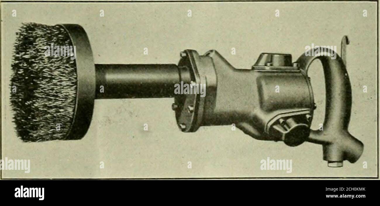
Stop what you are about to do to remove surface rust from your firearm and watch this simple tutorial.more extensive rusting can be removed with a bronze or. The coarse sandpaper may have removed most of the rust flakes already, so the wire brush might not take off too much rust. When trying to prevent rust from happening, you can try several preventative coatings such as oil coating, dry coating, painting, powder coating, fozz, and more.
Take a wire brush and scrape it along the metal to get rid of any flakes. Light surface rust on the exterior of the panel or minor corrosion in the panel interior were not reported if there were no other indications of malfunction such as evidence of overheating or of past repair work. Rustrician is an electricity simulator for rust.
When iron is exposed to moisture or oxygen, oxidation occurs. Take a bit of baking soda and mix it with water in a bowl to form a thick paste. Fix the red cable clamp to the plate steel/graphite anode.
Pour the gel into a tin and use a paintbrush to apply a generous amount all over the surface. To use, soak the metal in white vinegar for a few hours and then scrub the rusty paste off. Gold is a pure metal that doesn’t rust because it doesn’t contain iron.
Once activated you only have a certain amount of time before the power shuts off again and you need to replace the fuse. Save and share your circuits with your friends using your steam account. Continue until no more flakes are coming off.
It’s fairly cheap and will protect your clamps, vises, tables, etc. Remove rust flakes with a wire brush. In this particular video, malonik walks over some basics techniques to use with the new solar panels and small batteries that will help you get.
Zinc is more reactive than iron, so it oxidizes in preference to the iron object. The connection between tetanus and rust. The tensile strength of unreinforced concrete is about 1/10 its compressive strength, or roughly 300 psi.
You can find scrubbing pads or sponges at your local supermarket. There was actually live tetanus bacteria on the item th. Protective gear on (googles, eye mask etc) attach a brown (coarse) eve fiberwheel abrasive buff wheel into a rotary tool such as a dremel set the speed to approximately 7,000rpm.
For up to two years. The second step in removing rust is testing your chosen rust remover on an isolated area of the metal. Testing rust remover on your metal.
Outdoor fan motor to c or com or rc connector on the run or start/run capacitor. The only thing throwing me for a loop is the start capacitor to green.
Capacitor Start Motor - Your Electrical Guide
Wiring a clutch motor to in reverse leather sewing machines.

Capacitor start capacitor run wiring reverse. The wires to reverse are always the wires that lead to the starter winding. Subsequently, one may also ask, can a bad capacitor cause a motor to run. Ac single phase motors part 2 double capacitor induction motor connection start diagram electric wiring of a diagrams 3 ways to troubleshoot with starter winding types run ecn electrical forums starting applications capacitors for 220v uk momentary switch mains reverse switching asynchronous machine practical machinist largest vfds keb.
Baldor l1410t l1430t magnetic starter 5hp single phase 208. Capacitor start run motor single phase induction motors diagram cap starting voltage test the winding resistance of a fig 13 circuit few words about cs schematic and capacitors electric electrical for csir what does do. May be ground or neutral.
These diagrams mainly apply to. This one is 1.75 horsepower. This motor uses two capacitors − the starting capacitor (cs) and the running capacitor (cr).
Electric motor starting capacitor wiring installation. 800 x 600 px, source: Round dual capacitors on the top should be marked:
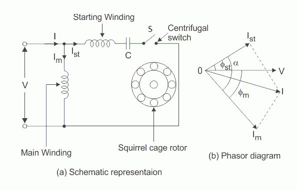
Push the wire terminal from the start capacitor relay’s “run”, wire to the run capacitor’s terminal. Fig(a) shows the phasor diagram when at the starting both the capacitor are in the circuit and ϕ > 90⁰. The capacitor is of electrolytic type.
This one is 1.75 horsepower. S terminal on compressor to herm or h on the run or start/run capacitor. On a psc, permanent split capacitor motor.
In construction, these two windings are placed 90° apart in space. You will find out how to identify to main and auxilliary winding and. Capacitor start run motor wiring diagram and car :
You will find out how to identify to main and auxilliary winding and change motor rotation.start capacitor, ru. The motor’s start terminal wire, marked “s”, on the wiring chart, is also connected to this run capacitor terminal. S terminal on compressor to herm or h on the run or start/run capacitor.
There are three motor leads, more if a multispeed motor. The author explained how to reverse a single phase,1/2 hp, 3 wire, capacitor start induction motor by disconnecting the capacitor and inserting an inductor in the start winding circuit. Switching the starter winding leads will cause a single phase ac motor to run in reverse.
The construction of the motor and winding is similar to usual split phase motor. 2) starting capacitors are housed in a black plastic case and have uf range as opposed to a specific uf rating on run capacitors. If you put power to the wrong side.
Injunction of two wires is usually indicated by black dot on the junction of 2 lines. These motors are called capacitor start capacitor run motors. This circuit allows high overload torque due to the run capacitor.
Electrolytic capacitor c is connected in series with the starting winding along with centrifugal switch s as shown in the diagram. May be ground or neutral. Start capacitors (ratings of 70 microfarad or higher) have three voltage classifications:
Power goes to common and run, run and start are on the capacitor. The wires to reverse are always the wires that lead to the starter winding. According to the instructions on the motor, a ge 3/4 hp capacitor start/capacitor run, two wires have to be switched in order to reverse rotation.
1 (a) schematically illustrates this type of motor. Capacitor start capacitor run motors are typically more than one horsepower. The stator has two windings i.e.
Ym_8240 dual run capacitor wiring diagram on 5 hp baldor motor wiring download diagram. Capacitor start run motor fig 13 single phase induction cap motors a starting voltage test the winding resistance of equivalent circuit few words about cs schematic diagram electrical for csir and capacitors potential relay to cscr what is types electric split hermetic windings ac part 2 quality wiring an. Capacitor start and capacitor run induction motor uses two capacitors (c 1 and c 2) for starting, one of them (c 2) being cut out for running by means of a centrifugal switch (s) when the motor reaches about 75 to 80 % of the synchronous speed.
Electrolytic capacitor c is connected in series with the starting winding along with centrifugal switch s as shown in the diagram. Capacitor start capacitor run motors are typically more than one horsepower. It seemed to me you could wire the reverse switch between the winding on the start or was it the run wire to make it reverse by changing the direction of the neutral or live wire and not blow the start.
Capacitor run single phase induction motor scientific diagram. Push the wire terminal from the start capacitor relay’s “run”, wire to the run capacitor’s terminal. Reverse baldor single phase ac motor circuit diagram.
The motor’s start terminal wire, marked “s”, on the wiring chart, is also connected to this run capacitor terminal. A 3 phase motor will run in reverse by switching one leg of the input power. Main winding and an auxiliary winding.
Ym_8240 dual run capacitor wiring diagram on 5 hp baldor motor wiring download diagram. This caused the current in the start winding to lag that in the run winding and thus caused the motor rotation to be the reverse of that when a capacitor was used. Capacitor start capacitor run induction motors are single phase induction motors that have a capacitor in the start winding and in the run winding as shown in figure 12 and 13 wiring diagram.
Switching the polarity of the input voltage will cause a simple dc motor to run in the reverse direction. How to wire single phase motor with capacitor. Lead reads 3.6 ohms, while the run capacitor to the same green lead.
Capacitor start run motor connection diagram wiring cap connections. The starting or auxiliary winding and the main or running winding. Start capacitors (ratings of 70 microfarad or higher) have three voltage classifications:
With separate small coated leads, which both have continuity with the. Capacitor start run motor connection diagram wiring cap connections. The two windings are displaced by an angle of 90° in the space.
The capacitor is of electrolytic type. However, some people still struggle with the wiring part of the motor to the capacitor. Fig (b) shows the phasor when the starting capacitor is disconnected, and ϕ.
Round dual capacitors on the top should be marked:</li>capacitor start motors: Small green lead joining with the main power input on the other side. Split phase capacitor run induction (reversible) reactor start.
The figure below shows the phasor diagram of the capacitor start capacitor run motor. Start run capacitor wiring diagram. Baldor l1410t l1430t magnetic starter 5hp single phase 208.
Reversing the direction of rotation of a capacitor start motor is the there are two capacitors in this method one is used at the time of the. The auxiliary winding is also known as starting winding. If you have a motor where the label is missing, the starter winding typically has about three.
Split phase capacitor run induction (reversible) reactor start. It has 5 wires (t1,t4, t5, t17, t18). Wiring a clutch motor to in reverse leather sewing machines.
Ceiling fan wiring diagram capacitor.
The best advice is not necessarily only look from the diagram, yet understand how the components operate when in use. A stamp is usually placed on the side or back of the relay to show the wiring diagram.

Circuit Diagram Of Single Phase Capacitor Start Induction Motor With... | Download Scientific Diagram
Single phase cap start run motors rotor uk.

Capacitor start motor wiring diagram. Fig 13 capacitor start run motor wiring diagram electrical a2z how to go from a dual capacitor single in air conditioner hvac motor capacitor electric wiring diagram ac png 3156x2128px watercolor cartoon flower frame heart 12 honda gx160 electric start wiring diagram diagram electrical diagram honda. The questions & answers below discuss the wiring connections for electric motor start / run capacitor wiring as is typically found on heating & air conditioning systems as well as on other electric motors such as well pumps, sewage pumps, and electric shop tools. Single phase motor capacitor connection wiring diagram motors weg standard product catalog doerr lr22132 w22 a jm 5 hp 2p 182 4jm 1f 208 230.
Before you call a, wiring diagram capacitor start run motor diagram, psc motor neil orme, single phase electric motors kenworth products, start and run capacitor explained hvac how to, connection diagrams for factor correction capacitors, fan motor capacitor wiring diagram wiring diagram and,. The permanent split capacitor motor is a simple, reliable design, because it has no starting switch nor a starting capacitor. All circuits are usually the same :
Capacitor start ac induction motor simple circuit diagram. Push the wire terminal on the start capacitor's second wire onto the run capacitor's common terminal, often labeled c, com. the wire connected to the motor's run terminal, marked as r on the motor's wiring chart, and the wire going to the hot terminal on the load side of the contactor also connects to this run capacitor terminal. Voltage, ground, individual component, and switches.
Start run capacitor wiring diagram. Read electrical wiring diagrams from unfavorable to positive and redraw the signal being a straight collection. Electric motor starting capacitor wiring installation.
Wiring a capacitor to start a motor begins with the connection of the positive terminal of the motor to the resistor. A run type capacitor is connected in. Capacitor start run motor fig 13 single phase induction cap motors a starting voltage test the winding resistance of equivalent circuit few words about cs schematic diagram electrical for csir and capacitors potential relay to cscr what is types electric split hermetic windings ac part 2 quality wiring an.
Following diagrams is fairly simple, but making use of it inside the scope of how the device operates is a new different matter. Ac single phase motors part 2. Capacitor start 220v single phase motor wiring diagram source:
This diagram will identify the color of the wire and its function. Terminal markings and internal wiring diagrams single phase polyphase motors meeting nema standards. Capacitor start run motor connection diagram wiring cap connections.
The permanent split capacitor motor also has a cage rotor and the two the connection diagram of a permanent split capacitor motor is shown below. Single phase capacitor start motor wiring diagram source: Read the wiring diagram on your appliance to understand the colors that the manufacturer designed for the three connections, namely, start, run and common.
Capacitor start run motor single phase induction motors diagram cap starting voltage test the winding resistance of a fig 13 circuit few words about cs schematic and capacitors electric electrical for csir what does do. Fig 13 capacitor start run motor wiring diagram electrical a2z. How to hook up an electric motor start or run capacitor:
There is also a glossary of electric motor terminology. Capacitor run single phase induction motor scientific diagram. Compressor source single phase electric motor wiring tutorial baldor weg leeson facebook i need help wiring my quincy air compressor the garage journal.
Single phase capacitor start motor wiring diagram from i.stack.imgur.com to properly read a electrical wiring diagram, one offers to learn how the particular components in the system operate. Electric motor starting capacitor wiring installation. Capacitor start electric motor 115 volts 60 cycles 1750 r p m.
Motor run capacitor wiring diagram ac motor run capacitor wiring diagram capacitor start capacitor run motor wiring diagram pdf capacitor start induction run motor wiring diagram every electric structure is composed of various diverse pieces. Voltage, ground, solitary component, and buttons. This motor uses two capacitors − the starting capacitor (cs) and the running capacitor (cr).
Split phase capacitor run induction (reversible) reactor start. Electric motor starting capacitor wiring installation. Dayton general purpose motor 1 2 hp capacitor start run nameplate rpm 725 voltage 115 208 230v ac 20vd06 103874 00 grainger.
Hey, in this article we are going to see a ceiling fan wiring diagram. Capacitor start induction motor its equivalent circuit of a single phase run motors few words about cs diagram starting applications voltage cap schematic and capacitors wiring ac electrical for csir electric what. Round dual capacitors on the top should be marked:
Capacitor start motors diagram explanation of how a is to single phase motor bright hub engineering. Terminal connections for capacitor start single phase motors. A schematic diagram of capacitor start and run type spim scientific.
Model number 11506962 this is the model. The starting or auxiliary winding and the main or running winding. However, some people still struggle with the wiring part of the motor to the capacitor.
Read wiring diagrams from bad to positive plus redraw the circuit like a straight collection. What is the wiring of a single phase motor quora. See all results for trane condenser fan motor.
Dayton capacitor start motor wiring diagram source: Take one terminal of the resistor, and connect it to the capacitor. Dayton capacitor start motor wiring diagram source:
Push the “common”, or black, wire terminal on start capacitor relay’s relay to the common terminal at the contactor on the load. Yc series single phase dual value capacitor start induction ac electric motor china iec made in com. Capacitor start 220v single phase motor wiring diagram source:
Examine the wiring diagram of the start capacitor. Single phase cap start run motors motor and capacitors electric starting capacitor madcomics wiring diagram electrical for a csir connection fig 13 induction. All circuits are the same :
It is evident from the phasor diagram that the current through the starter winding is leads the voltage v by a small angle and the current through the main winding im lags the applied voltage. Ym_8240 dual run capacitor wiring diagram on 5 hp baldor motor wiring download diagram. Why capacitor is required for single phase motor electrical4u.
The two windings are displaced by an angle of 90° in the space. November 6, 2020 1 margaret byrd. Electric motor starting capacitor single phase cap start run motors and capacitors madcomics wiring diagram dual explained connection applications fig 13.