You may use two 30 amperes circuit breakers for two thermostats and heating elements instead of one 50 amperes circuit breaker. Power flows from the red wire, but not continuously so the common wire is necessary to complete the process.

Thermal Protector For Switch Power Supply - China Thermostat, Temperature Controller | Made-In-China.com
Reconnect the red and white wire, tighten down the set screw, and put the control panel back on.
Thermostat switch power supply connection. The thermostat will be next to the light switch so won't take much figuring out for the next guy. On the other hand, the neutral (n) is directly. If you have a c wire, place it into the c terminal on your wall plate.
If you are using this method, ensure you install your thermostat close enough to a plug. A thermostat is a simple switch. In a linear power supply, the power transistor is operating in a linear mode.
For the y, y1, and y2 wires, y or y1 will go to the y terminal, and y2 will go to the y2 terminal. 2.1 the basic principle of pwm switching power supply. It should have a barrel plug on the end of its cord which fits into the.
Voltage divider circuit is formed by the thermistor and a variable resistor. This wire will go to the g terminal on your new thermostat. Here is a photo of the interior of a primary controller for a heating boiler, a honeywell l8148e aquastat.
L 4 and t 2 terminal of both thermostats are connected to the upper and lower heater. This will be used to connect the thermostat to the relay box. 120v ac single phase single element water heater thermostat wiring.
It can be ac or dc output, but it's voltage needs to match (sort of) the coil on your relay (i'm using 9vdc to control a 12v coil). The common wire is usually blue or black, but that is. The remaining wires from the furnace connect to the thermostat, as usual.
As i understand, a constant voltage supply will overload an led if there is no resistive load, so it will supply as much current as it's capable of. Circuit diagram of thermistor circuit: If your existing thermostat is not powered by 24 vac, you may have to connect the common wire at the hvac unit.
In short the rf thermostat has the following functions: Remove the motherboard of the old 2 wire thermostat and put the new 2 wire thermostat in its place. To find and test the thermostat's power supply provided by a low voltage transformer see low voltage transformer test.
The purpose of a c wire is to ensure continuous flow of 24 volts ac power supply to the thermostat. You could replace a thermostat with a light switch, and the heating equipment would never know the. Testing and connecting 24vac common wire the powershift smart thermostat requires a 24 volt ac (24 vac) common wire (c/x wire) to supply power.
Follow the instructions below to determine if your home has the required 24 vac common wire. If the thermostat controls an air conditioning system, turn it down as far as it will go. Back in the olden days, thermostats were just on/off switching devices and they used to draw the necessary.
Displaying and setting the various parameters of the thermostat sensor module. It has a 24v transformer to power the 120v relay switch, and the control wire connections are t & t. They usually need a common wire or c wire in thermostat to provide this continuous power.
Step 6 insert the power cord into the power connector. It is quite easy to understand the working process of the switching power supply. While you're at it, toggle the fan switch from auto to the on position, and if the thermostat has power, you should hear the.
The g terminal controls the fan relay and is responsible for turning the blower fan on and off automatically or manually via the thermostat. But if a constant current supply is connected to a load, won't it only supply the current needed? The same power supply is connected to the lower thermostat and heating element following by the same circuit breaker and switch.
Unscrew the two wires from the terminals. Switch the rf panel relay on and off based on the room temperature and the desired temperature. When i teach, i even have the class repeat, a thermostat is just a switch.
The thermostat is the control device that provides a simple user interface with the internal workings of your homes climate control system. Let's take a look at the g wire. In this wiring connection, the phase line (l) from 120v/240v main panel (sp breaker) is connected to the l1 screw on the thermostat and then leaving the t2 terminal which is further connected to the single heating element.
The circuit compromises of a voltage divider circuit and output “on and off” switching circuit. Alternatively, you can plug the device into a power socket using the power cable and plug included in the box. When the contact is open the terminals of the rectifier bridge see the 24vac voltage of the hvac transformer and convert the ac power to dc power, as previously described.
One simple way to check is to turn up the thermostat as far as it will go and wait a minute to see if the furnace turns on. (refer to the manufacturer’s installation instructions for your specific. Step 8 turn on the power at the power source.
The module requires 12v to operate, so the 12v and the ground could be connected to an external power supply unit.
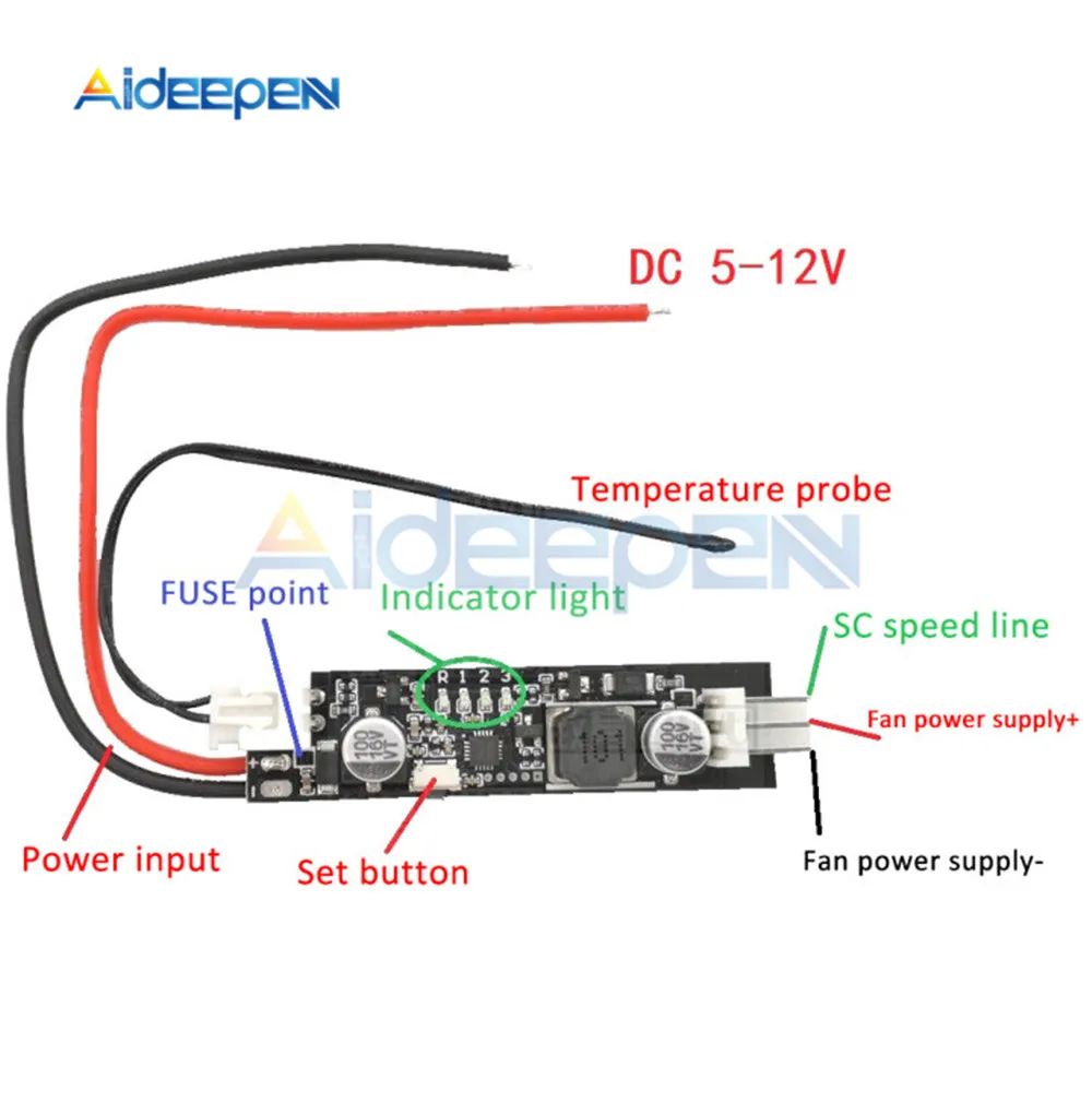
2-3 Wire Dc 5V 12V Pwm Fan Temperature Controller Governor Speed Controller Switch Temperature Control Governor Module - Motor Controller - Aliexpress

Buy Stc-1000 Dc 12V Digital Temperature Controller Online
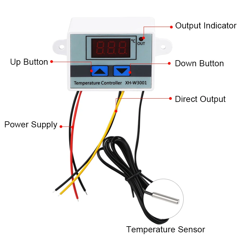
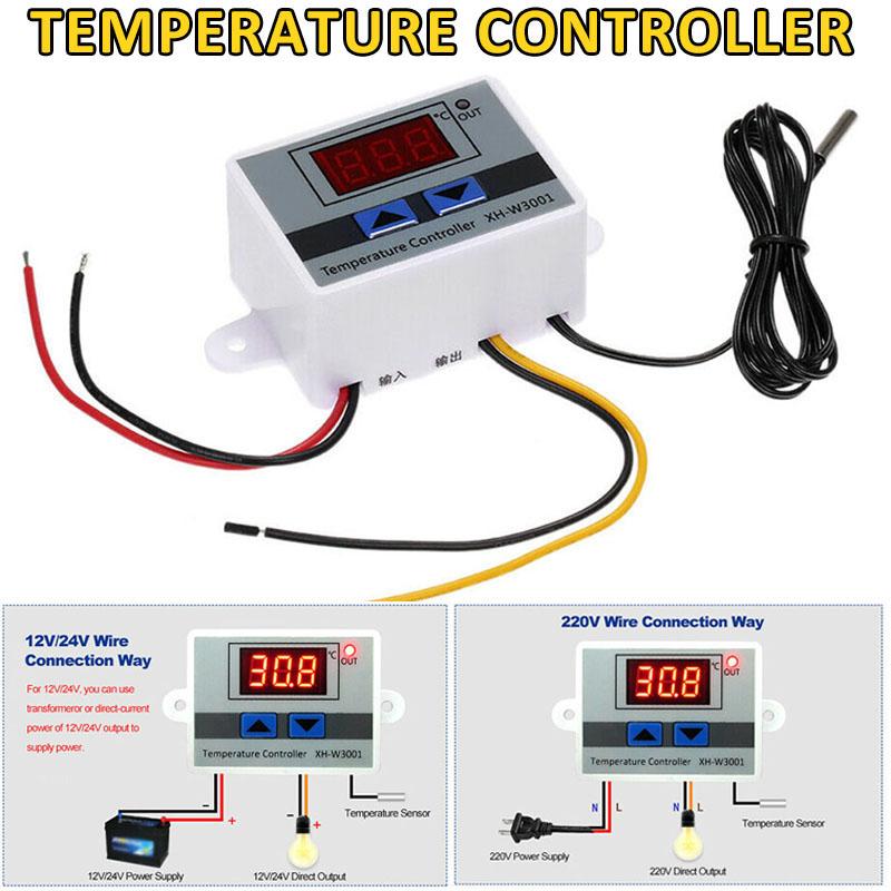
10A 12V 24V 110V 220Vac Digital Led Temperature Controller Xh W3001 Untuk Inkubator Cooling Heating Switch Thermostat Ntc Sensor|Alat Tangan Set| - Aliexpress
How Am I Supposed To Use This Thermostat (Stc-1000) If It Has 12V Dc Input, But 220V Ac Output For Heating? Is The Output Supposed To Be Wired Directly To A Plug(Uk)? -
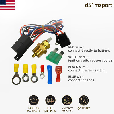
Electric Radiator Cooling Fan'srelay Kit Thermostat Temperature Switch Universal | Ebay